

Microcontrollers are used for a variety of purposes. Some applications require high speed, high performance, and continuous full operation, while others require only partial operation at specific cycles. Renesas has been studying these use cases for a number of years and designed the extremely power-efficient RA2E3 to allow designers various means of reducing the MCU power consumption with its power-saving functions. This allows microcontroller-based electronic products to be power efficient and environmentally friendly as expected by end users. RA2E3 provides four main power-saving functions which can be used either separately or in combination:
- Three different low-power operating modes
- Four different power-control modes
- Switching the clock frequency to an appropriate speed
- Stopping unnecessary modules for a specific duration
Low-power operating modes
RA2E3 provides the following three different low-power modes:
- Sleep mode
- Software Standby mode
- Snooze mode
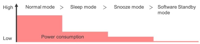
The MCU can be programmed to be transited among these modes automatically when the required conditions are satisfied. The maximum supply current in the Normal mode with a certain condition (high-speed clocks, all peripheral clocks are enabled, etc.) is 12mA while the typical supply current in the Software Standby mode in a certain condition (all SRAMs are on, all peripheral modules are stopped, etc.) is 0.25µA. Supply currents in Sleep mode and Snooze mode lay between those in Normal and Software Standby modes based on the conditions like number of operating modules, clock frequency, etc. Power consumption in each mode can be roughly compared as in Figure 1. The transition method among low-power modes is depicted in Figure 2.

Sleep mode – in this mode, the CPU stops operating but the contents of its internal registers are retained. Other peripheral functions and oscillators do not stop by default, but the user can set up whether they are to be stopped or not.
For example, if the user needs to execute A/D conversion for a certain period in fast mode but CPU intention is not required in that period, the user can program MCU to enter Sleep mode with a high-speed conversion clock at the start of the A/D conversion and return to Normal mode when the A/D conversion is completed. In this example, the user saves unnecessary CPU power consumption during that period. Refer to the RA2E3 hardware manual for more details about entering into, operating in, and canceling the Sleep mode.
Software Standby mode – in this mode, the CPU, most of the peripheral functions, and oscillators stop. However, the contents of the CPU internal registers and SRAM data, the states of on-chip peripheral functions, and the I/O ports are retained. Software Standby mode allows a significant reduction in power consumption because most of the oscillators have stopped.
For example, if an MCU needs to wait for an external input like IRQ interrupt to initiate a specific operation and no other operation is required during that waiting period, the user can program the MCU to stay in Software Standby mode until the input is received, saving most of the unnecessary power consumption. Once the input is received, the target operation can be executed in Software Standby mode or after transit to either Snooze or Normal mode as required. It is possible to return to Software Standby mode again after the completion of the target operation and wait for the next input. Refer to the RA2E3 hardware manual for more details about entering into, operating in, and canceling the Software Standby mode.
Snooze mode – in this mode, the CPU stops operating but the contents of its internal registers are retained. Operation of most peripheral functions and oscillators are selectable. As depicted in Figure 2, direct transition to Snooze mode from Normal mode or Sleep mode is not allowed. Transition to Snooze mode should be made through the Software Standby mode. Direct transition to the Normal mode form Snooze mode can be made, however.
Let’s look at an example using the UART in Snooze mode. Before starting the UART communication, the MCU can stay in Software Standby mode saving power. When it starts to receive the UART data, the MCU can transit to Snooze mode and continue receiving data without waking up the CPU, unnecessary peripheral functions, and oscillators. Once the data receiving is completed, the MCU can return to Software Standby mode again and wait for the next UART data. Refer to the RA2E3 hardware manual for more details about entering into, operating in, ending and canceling the Snooze mode.
Power-control modes
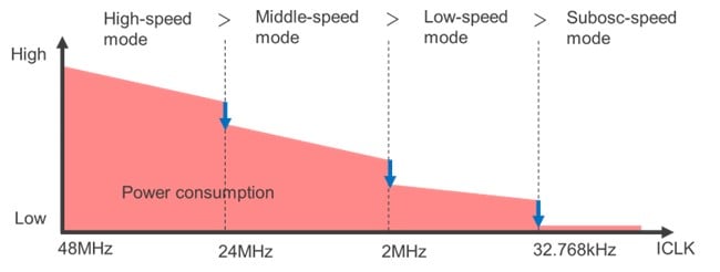
There are four power-control modes which are defined mainly based on the maximum operating frequency and the operating voltage range. The current consumption of memory (Flash/RAM) is reduced by controlling the memory reading speed according to the power-control mode. Users can select the power-control mode as it meets the appropriate operating frequency and power consumption. Power-control modes can be used in Normal, Sleep, and Snooze modes. Power consumption in each mode is shown in Figure 3.
High-speed mode – in this mode, the maximum operating frequency and voltage range during flash reading are 48MHz and 1.8V to 5.5V respectively. The maximum supply current in this mode with a certain condition (operating in Normal mode, all peripheral clocks are disabled, CoreMark code executing from flash) is 4.80mA.
Middle-speed mode – in this mode, the maximum operating frequency and voltage range during flash reading are 24MHz and 1.8V to 5.5V respectively. However, the maximum operating frequency is 4MHz when the operating voltage is 1.6V to 1.8V. The typical supply current in this mode with a certain condition (operating in Normal mode, all peripheral clocks are disabled, CoreMark code executing from flash) is 2.60mA.
Low-speed mode – in this mode, the maximum operating frequency and voltage range during flash reading are 2MHz and 1.6V to 5.5V respectively. The typical supply current in this mode with a certain condition (operating in Normal mode, all peripheral clocks are disabled, CoreMark code executing from flash) is 0.30mA.
Subosc-speed mode – in this mode, the maximum operating frequency and voltage range during flash reading are 37.6832kHz and 1.6V to 5.5V respectively. The typical supply current in this mode with a certain condition (operating in Normal mode, all peripheral clocks are enabled, etc.) is about 5µA.
Clock switching
The frequency division ratio can be selected for the system clock (ICLK). When a high-speed clock is not required, the user can switch to the appropriate lower-speed clock and save power consumption. Clock division ratios are 1, 2, 4, 8, 16, 32, and 64.
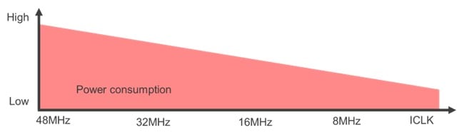
The lower the frequency, the lower the current consumption. But in terms of power performance (mA/MHz), 48MHz is the most efficient (100µA/MHz = 4.8mA/48MHz). In general, for applications that require higher calculation processing and CPU performance, lower power consumption can be achieved by setting the frequency higher and shortening the CPU processing time in Normal mode. On the other hand, for applications like control systems, current consumption can be reduced by setting the frequency to a lower value in Normal mode.
For example, the typical supply currents when the ICLK is 48MHz, 32MHz, 16MHz, and 8MHz are 4.80mA, 3.45mA, 2.05mA, and 1.40mA respectively under the condition of following power-saving functions. Low-power mode: Normal mode, Power-control mode: High-speed mode, module stopping: all the peripheral clocks are disabled.
The clock division ratio 1, 2, 4, 8, 16, 32, and 64 can be selected for the peripheral clocks (PCLKB, PCLKD) too.
Module-stop function
Power consumption can be saved by stopping non-operating modules or their clocks with the following register settings:
- Operation of DTC, I2C, SPI, SCI, CAC, CRC, DOC, ELC, AGT, GPT32n, GPT16n, POEG, ADC120 modules can be stopped by the setting of the MSTPCRn (n: A, B, C, D) registers
- Register R/W clock for RTC, WDT, IWDT can be stopped by the setting of the LSMRWDIS register
- Operating clock for MPU, Debugging, BPF can be stopped by the setting of the LPOPT register
- 8KB out of 16KB of SRAM can be powered off in Software Standby mode by the settings of PSMCR register
Combination of each power-saving function
More power savings can be achieved using the power-saving functions in combination. The table details five cases that are just a few examples among the many possible combinations.
| Low-power mode | Power-control mode | Clock-switching | Module-stopping | Supply current | |
|---|---|---|---|---|---|
| Case 1 | Normal mode | High-speed mode | ICLK: 48MHz | All peripheral clocks: enabled | 12.0mA (Max) |
| Case 2 | Sleep mode | High-speed mode | ICLK: 48MHz | All peripheral clocks: enabled | 4.15mA (Typ) |
| Case 3 | Sleep mode | Low-speed mode | ICLK: 2MHz | All peripheral clocks: enabled | 0.31mA (Typ) |
| Case 4 | Sleep mode | Low-speed mode | ICLK: 2MHz | All peripheral clocks: disabled | 0.14mA (Typ) |
| Case 5 | Software Standby mode | - | ICLK: 32.768kHz | All peripheral/SRAMs: stop | 0.25µA (Typ) |

For additional information on the ultra-low power RA2E3 MCUs, please visit renesas.com/ra2e3.
Read more about RA2E3 low-power operating modes in the RA2E3 hardware manual.