

Electrical motors facilitate physical motion, actuation, and control, which are indispensable for a wide range of applications. Due to their frequent use, electric motors are one of the primary targets for energy conservation; it is estimated that they consume nearly half of the electricity generated globally. It is therefore not surprising that consumers, businesses, and legislators are extremely concerned about the inefficiency of electric motors. A multitude of laws and regulations have been implemented worldwide with the goal of setting specific energy objectives and enhancing motor efficiency. To successfully achieve these objectives, further consideration must be given to the development of more dependable and efficient motors and control methods.
Driving Motor Efficiency
As the industry endeavours to improve the efficiency of motor drives, it is crucial to comprehend the types and characteristics of various motor technologies. For an effective motor control design, the selection of a particular motor type and its control system's components is crucial. Currently, the brushed DC motor is the most popular form of DC motor, but as this market continues to expand, the brushless DC (BLDC) motor is becoming the most practical option due to its reliability, efficiency, and small size. In rigorous motor applications, the BLDC motor has distinct advantages over other motor types in terms of optimizing efficiency and size. BLDC motors lack brushes, require less maintenance, and provide enhanced performance.
The other main motor type is the permanent magnet, which provides high coercive force to enable high torque density for the most demanding motor control applications. Three-phase synchronous motors (PMSM, PMSG) and single- or three-phase brushless DC motors are utilized in a vast array of applications, such as servo motors, robotics, hand-held power tools, battery- or line-fed appliances, industrial prime movers, fans, pumps, and wind turbine generators, to name a few. The control of torque, speed, or position of these devices is dependent on the conveyor rotor position information. Hall effect to determine the rotor magnetic field or absolute encoders are used for this purpose; however, a multitude of sensorless schemes have been developed for these machines to reduce cost and enhance reliability.
In an induction machine, three-phase voltage is supplied directly to the stator winding, inducing a voltage in the rotor conductors, and torque is generated by the interaction of rotor current and stator flux. Due to their manufacturing process and minimal maintenance requirements, these machines, such as motors for industrial applications or generators in wind turbines, are potentially the least expensive alternatives. Without a rotor position or speed sensor, they can be readily started and regulated in an open-loop speed regulation system by variable frequency inverters. The table below highlights various motor types and the main operational areas associated with efficiency, reliability, and performance compromises.
Table 1. Types of Motors
| DC Machine | Brushless DC Machine (BLDC) | Permanent Magnet Synchronous Machine (PMSM) | Induction Machine (IM) |
|---|---|---|---|
Advantages
| Advantages
| Advantages
| Advantages
|
Disadvantages
| Disadvantages
| Disadvantages
| Disadvantages
|
The most common techniques and applications for motor control are described in Table 2. Defining and comprehending the motor application is crucial for selecting the optimal controller for analog and digital motor control solutions. Each application may employ motor control techniques requiring the adjustment of one or more control loops (torque, speed, or position). The method used to control voltage, which establishes the speed, and current, which controls torque, determines precision and efficiency.
Table 2. Motor Control Techniques and Applications
| Motor Control Techniques and Applications | ||
|---|---|---|
| Control | Technique | Applications |
| Speed | Rotate at constant or multiple RPMs | Pumps, fans, compressors |
| Torque | Maintain force while changing direction | Doors, conveyors, drive systems, industrial machines |
| Position | Move to the precise location | Robotics, radar, satellite communications, drones |
To increase the efficacy of motor drives, it is necessary to consider several factors, including the motor's construction, system components, and drive method. The torque-speed relationship is one of the most important characteristics of motors, as it defines the motor's ability to produce torque at various speeds. Additionally, the inertia and load of the motor influence its performance under various operating conditions. Like the mechanical inertia of the system, the resistance and inductance of the motor define the electromagnetic inertia of the motor.
Accelerate Your Motor Control Design with Renesas
Microcontrollers, microprocessors, and digital signal processors (DSPs) have played a significant role in the rapid growth of the motor control field, which has been fueled by advances in semiconductor electronics. This indicates that the electrical drive controls have become more precise, as not only the DC current and voltage but also the three-phase currents and voltages, are now managed by a combination of MCUs and software algorithms.
Renesas offers comprehensive solutions for motor and inverter control to support the entire development process. We offer every essential component required to design an optimal and effective motor control system. Our motor control solutions can be broken down into four primary components:
- Motor Control Devices: Microcontrollers, ASSPs, and other critical analog and power components
- Hardware Support Ecosystem: A wide range of solution kits, starter kits, and evaluation kits.
- Motor Control Algorithms: A library of software examples and application notes
- Motor Control Development Tools: Easy-to-use complete software development tool and workbench that allows you to develop motor software by simply following the workflow.
Motor Control Devices
Renesas offers an extensive selection of application-specific standard products (ASSPs) for motor control based on its high-performance RX, RL78, and RA MCU families. These products are designed to meet a variety of motor control needs for virtually any embedded application. Several important characteristics are highlighted below:
- High-Performance CPU: Single precision floating point unit (FPU) operating at core frequencies of 32MHz up to 200MHz and dedicated arithmetic unit for trigonometric functions (simultaneous sine, cosine, arctangent)
- Enhanced PWM Functionality: 32-bit general-purpose timers (GPT) facilitating single or three-phase complementary 0-100% PWM outputs to control multiple inverters with dead-time, PoE for fail-safe operations, and high-resolution PWM suitable for ultra-high-speed BLDC drives.
- Rich Analog Peripheral: Up to three 12-bit units of sample-and-hold ADCs with on-chip programmable gain amplifier (GPA) enabling a high-precision analog front end (AFE) combination on a single silicon chip to get rid of common mode noise. The DAC unit with a matching 12-bit resolution can be used to interact with other components and enables motor protection functions.
- Communication Interfaces: Offering multiple communication interfaces such as full-speed USB 2.0 inc. Host or On-the-Go (OTG) controller, ISO 11898-1 CAN, multi-channel SCI, SPI, 400kbps SMBus enabled I2C. These interfaces enable seamless communication with external devices and systems, such as sensors, actuators, HMIs, and motor control networks suitable for connected end products.
- Safety, Protection, and Encryption Features: Renesas MCUs for motor control applications typically incorporate safety and protection features: supporting Class B (fail-safe) software for household appliances (IEC 60730 compliant), memory protection, cyclic redundancy check (CRC) calculator, and Trusted Secure IP (TSIP-Lite).
- Scalability: MCUs come in a range of models with varying performance levels and pin counts (48 up to 144 pins LQFP, LGA, and BGA packages) with the same pin assignment concept. This scalability allows developers to choose the most suitable MCU for their motor control application, balancing performance requirements and space and cost considerations.
Motor Control Algorithms
BLDC and other varieties of motors are controlled using motor control algorithms. For instance, the control algorithm must provide pulse-width modulation (PWM) voltage to control motor speed, a mechanism to commutate the motor, and a method to estimate rotor position using back electromotive force (EMF) or Hall sensors. Renesas provides application notes and software examples to accelerate the development of motor control solutions based on our highly optimized microcontroller devices. In addition, for BLDC, AC, stepper, and universal motors, Renesas offers comprehensive solution support (Figure 1) including software algorithms, application examples, and a range of reference designs to reduce your time to market.
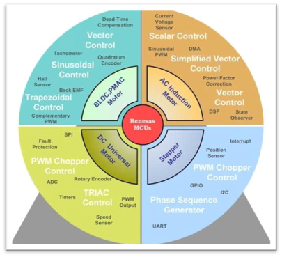
Figure 1. Motor Control Algorithms
Motor Control Development Tools
The Renesas e2 studio integrated with Renesas QE (Quick & Easy – Figure 2) utility is designed to facilitate the development and debugging process for Renesas microcontrollers. It offers a variety of features and capabilities that streamline the development workflow and increase productivity. QE simplifies the development process by automatically generating initialization code and device drivers, visual pin assignment, and peripheral configuration, allowing embedded developers to concentrate on the higher-level application logic and rely on the generated code for device-specific configurations. Motor control function generation is a useful feature of QE that automatically generates optimized code for driving different varieties of motors, including brushless DC (BLDC), permanent magnet synchronous motors (PMSM), and stepper motors. It bridges the distance between motor drive engineers and embedded developers by allowing GUI-based visualization and debugging of motor control inputs and outputs.
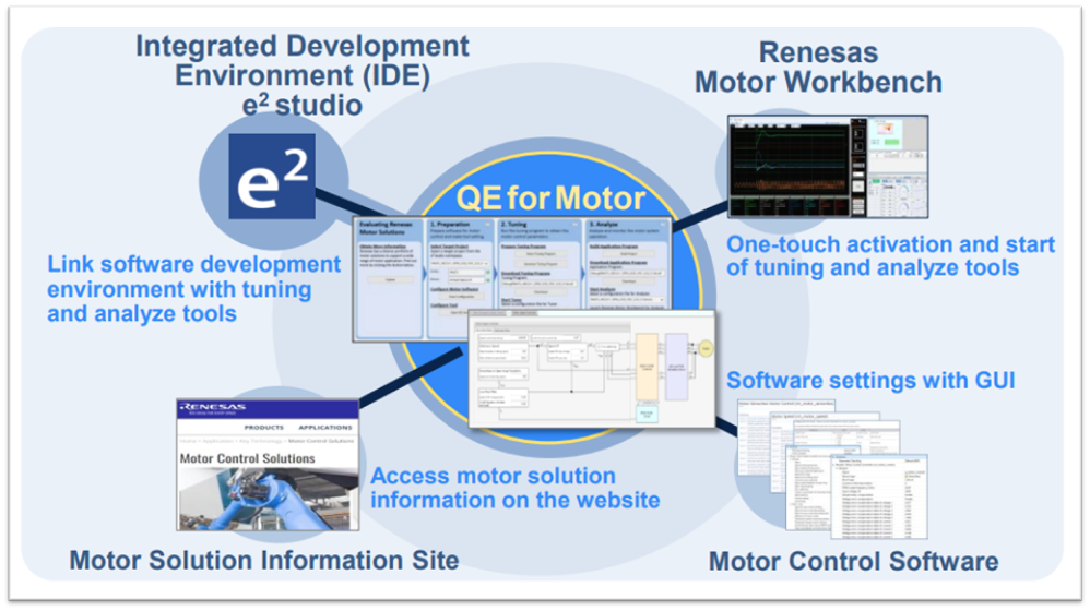
Figure 2. Integrated Development Environment with QE for Motor
Renesas offers a comprehensive operating environment and development tools to accelerate time-to-market and, more importantly, add value to your most demanding motor control applications.
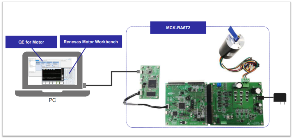
Figure 3. Renesas Motor Control Operating Environment
Given the high energy consumption of different motor-based applications, it is extremely important to find new ways to improve efficiency in the actual motor construction as well as related drive techniques. In addition, the control strategy is a crucial aspect of enhancing the energy efficiency of electric motors through the use of innovative methods and design capabilities. Renesas offers intelligent motor and inverter control solutions to support the entire development process while meeting efficiency objectives. Renesas is an ideal partner for the design of your next-generation motor control system as it provides all the essential components involved in the control of motor drives, as well as the related tools, extensive design resources, and solid technical support.