

The Serial Peripheral Interface (SPI) has for many years been one of the simplest ways to interface external devices, such as sensors and external memories to a microcontroller. The SPI interface uses a simple synchronous serial protocol; this can be considered as a large serial buffer shared between two devices, a master and a slave, allowing data to be clocked between one device and the other under the control of a shift clock generated by the master device.

The SPI interface is controlled by the master device, which can connect to one or more slave devices using four logic signals. These are normally known as:
- SCLK: Serial Clock (clock signal generated by the Master)
- MOSI: Master Out Slave In (data output from Master)
- MISO: Master In Slave Out (data output from Slave)
- CS: Chip Select (active low signal generated by the Master to address individual devices and initiate the data transfer between them)
On the RA family of microcontrollers, SCLK is sometimes also known as the RSPCK, and the CS signal is known as the Slave Select Signal (SSL).
SPI is a non-standard standard, different implementations developed many years ago by semiconductor vendors such as Motorola and National Semiconductor have resulted in different naming conventions for these logic signals, depending on the device and the manufacturer. To complicate matters more, the different vendors developed SPI peripheral devices that can communicate in several different “flavors” of SPI which can complicate setting up communications between multiple devices.
Different slave devices may be designed to communicate by shifting data out during the rising or falling edge of the clock, either immediately when the CS becomes valid or on the next cycle, this is known as the clock polarity, and the data is sampled on the corresponding falling or rising edge, this is known as the clock phase.
Slave devices can come in any of these flavors so our SPI master must also be able to communicate in all the different flavors to be able to talk to every potential SPI slave device. In addition, SPI slave devices may expect to transfer data to either LSB or MSB first, with a selectable data length. With the use of multiple pins as Chip Selects, it’s possible to connect several different peripheral devices to one master and select each individually to initialize communications.

Using an SPI master on your microcontroller to interface your MCU to several SPI peripherals, all with different communication requirements, can become quite complex. This can greatly increase the size of the software driver required for the SPI interface and the need to support different flavors can also mean that you need to reconfigure the SPI interface between every data transfer you make to a different slave device.
The SPI interface on the RA family is quite a complex peripheral, as it must cope with the wide variety of different communications methods covered by SPI. The SPI interface can be programmed with a choice of clock polarity or clock phase, a programmable data transfer length selectable between 8 and 32 bits, a programmable bit rate, and the ability to directly control various SPI timings such as the delay before the Chip Select is released and the delay until next access. Full and half duplex, both transmit-only and receive-only operations are supported.
The RA SPI interface can automatically control up to four Chip Selects, allowing up to four devices to be handled automatically. Additional devices can be managed with software support using standard I/O pins. The SPI interface on the RA MCU also implements a selectable pin invert function.
The SPI interface on the RA has 128-bit transmit and receive buffers, which allow the use of up to four data frames transferable in one round of transmission or reception. These data frames are user selectable between one and four for each transfer.
A wide variety of errors can be detected by the SPI interface which can generate an interrupt; and, interrupts can also be generated on receive buffer full, transmit buffer empty, and transmission complete. These events can also be used to trigger a Data Transfer Controller (DTC) or Direct Memory Access (DMA) transfer.
Finally, the SPI interface can work in master mode or can be used in slave mode with an external master device.
An SPI transfer is triggered by the writing of data into the SPI data register. This register can be accessed on a byte, word, or longword basis and the SPI interface will automatically transfer the data into the transmit buffer and starts the serial transfer.
If you are communicating with multiple devices, perhaps using different flavors of SPI, with different baud rates, you need to set up the SPI interface each time and trigger the transfer, this can take up a lot of CPU overhead, so it would be much easier if we had a way to make this set up and the communications automatic.
The Renesas Serial Peripheral Interface (RSPI) interface implemented on the RA 32-bit MCU family, provides an advanced command sequencer in the SPI logic to allow you to set up a series of automatic transfers between different SPI slave devices and to reconfigure the interface between each transfer. This can greatly reduce the requirements for the SPI interrupt service routine, as you no longer need to reconfigure the SPI interface between each transfer to a different device, and it can also speed up the transfer times for the same reason. Using the command sequencer to manage the SPI interface can also save power in your application, as your CPU can be asleep while the command sequencer automates the collection of data from different devices, using either the on-chip DMA controller or the DTC to fetch data from the on-chip SRAM to be sent or to load the received data into buffers in the SRAM to be analyzed later.
The SPI command sequencer allows a sequence of up to eight transfers to be executed in a looped sequence. After the sequence is completed, it will start again with the first command, you can see the available sequences below.
Sequence Length is 1 (n = 0→0→…)
Sequence Length is 2 (n = 0→1→0→…)
Sequence Length is 3 (n = 0→1→2→0→…)
Sequence Length is 4 (n = 0→1→2→3→0→…)
Sequence Length is 5 (n = 0→1→2→3→4→0→…)
Sequence Length is 6 (n = 0→1→2→3→4→5→0→…)
Sequence Length is 7 (n = 0→1→2→3→4→5→6→0→…)
Sequence Length is 8 (n =0→1→2→3→4→5→6→7→0→…)
For each command, you can set functions such as bit rate, clock polarity and phase, slave select logic level, data transfer length, and Most Significant Bit (MSB) or Least Significant Bit (LSB) first. For each command, you can also select which Chip Select pin to use for each command, so selecting a specific slave device, you can set how long after the transfer is complete the Chip Select signal is released, and you can set the access delay after the transfer before the start of the next transfer.
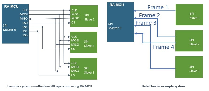
The diagram above shows an example system using SPI to connect the RA Master MCU to three slave devices. We can imagine such a system where the RA is collecting data regularly from several sensor devices, such as pressure, humidity, or temperature sensors. The command sequencer allows us to manage the collection of data from these sensors automatically with little CPU overhead. The command sequencer is used to manage the communications between these devices; in this example, we use a sequence length of four, as the sequence length is independent of the number of accesses to each slave device. In this sequence, we access Slave 2 twice, effectively at double the rate of the other two slave devices. Each data transfer between the master and slave has its own parameters, set up as part of the command structure.
The use of the command sequencer significantly reduces the CPU load to manage the reading of serial devices using the SPI interface, and when combined with the DTC or the DMA controller to automate the data transfer, this provides a powerful tool to manage data from external devices like sensors and memories completely automatically with minimum CPU intervention.
You can find out more about the SPI Interface implementation on RA microcontrollers and the SPI command sequencer in any of the RA device hardware manuals available for download from our website.